This specification outlines the details required to build HO Freemo Modules. It is intended to allow the assembly of large layouts running many trains in a prototypical manner. This is made possible by DCC and the use of DCC is assumed in this specification. A major consideration in producing this document has been to allow maximum flexibility for the module builder.

Recommended Specification for HO Scale Modules
Release 2 June 2014 (current as of 12.04.2020)
The first release of this specification was in 2011. Since then, the experience of using it to build and operate modules has suggested some changes, as have clarification questions raised by module builders. This second release (2014) of the specification addresses these and incorporates the following major changes:-
- Any type of throttle panel may now be used (see SE5.2 and Guidance note 3)
- Two (compatible) options for connections between modules are now allowed
- Clamping areas on end boards have been defined
- The requirement to have a “clean” throttle bus for multi-group meets has been added
- A section covering track-bed has been added (SP12)
- A discussion of the features of various throttle panels has been added (Guidance note 3)
- The section on multi-group meets (Guidance note 2) has been expanded to incorporate the latestthinking, including Wi-Fi throttles. This may be expanded later to include NMRA BUS as thisdevelops.
- A change history section has been added.

2 Key Features
-
- A module can contain any number of baseboards and the internal baseboard joints in a module do not have to conform to modular specifications.
- Modules are reversible.
- There is no restriction on module width other than at the module’s ends.
- There is no restriction on the length of modules, baseboards or adapter boards. However, if it is plannedto incorporate a new module into an oval with existing modules, then the length of the module (plus adapter boards, if any) should be made a multiple of four feet. However, note that it is anticipated that any large layouts will be end-to end or end-to-loop.
- A module can have any number of module ends. One for terminals, two for typical main lines, three for wyes, four for junctions, or as many as the builder requires.
- There is no requirement that the sides of a module should be straight, or parallel to each other.
- There is no requirement that the end-boards at opposite ends of a module should be parallel to eachother
- There is no restriction on making curved modules apart from the minimum radius requirements and theneed for a 6” straight at module ends.
- There is no restriction on the method of point control, but see SE3 as regards electrical arrangements.
- It is possible to build a minimal dcc system for local use. A more complete system will be needed for multi-group events but the additional circuits for this can be temporary ‘on the day’ if that is preferred, rather than being built into the modules.
This specification assumes that dcc will be used. However, analogue modules such as those built to the current NMRA specification can be used provided that they have an adequate track bus (See Guidance note 1). It also assumes a degree of accepted practices, e.g. all end boards are set accurately at 90 degrees to the baseboard tops and thus the track. Also that adequate width of materials will be used for the construction of the modules, especially end boards where strength and rigidity will be needed most. In other words, common sense is assumed.
3 Acknowledgement
The specifications below are based on those of the RS Tower Group https://rstower.wordpress.com/module-info/. This group, with a large proportion of NMRA members, has the most advanced HO modular set up in terms of both current day standards such as DCC, adherence to prototype practice in design and operation, its overall size and potential to grow further. Their physical standards have been reproduced here with their permission.
However, the electrical specification has been made more comprehensive. Modules built to the specification in this document will work in RS Tower set-ups. RS Tower modules will work as part of a layout built to these specifications but may need some temporary wiring ‘on the day’.
4 Definitions
Baseboard Module
Adapter Board Specifications
An individual board carrying a section of model railroad. It may or may not meet these specifications.
A section of model railroad mounted on one or more baseboards. The outer ends of the combination of baseboards must meet the ‘Physical’ specification below. Overall, the combination meets the electrical specification.
A baseboard that allows modules built to this specification to be attached to those built to a different specification.
The specifications are those parts of this document that must be followed when building modules. Physical standards have designations such as SPnn; electrical standards are designated SEnn
5 Specifications
5.1 Module Requirements – Physical
A module must feature one or more modular ends. Modular ends come in two types to cater for single and double track – see SP2 and SP3 below. Modules are reversible.
SP1: Module shape restrictions
The module may be any length.
Apart from the end dimensions as defined in SP2 and SP3, the rest of the module can be any width.
The sides of the module do not have to be parallel and may be straight or curved.
The ends of the module do not have to be parallel but should be straight, flat and at right angles to the baseboard top. SP2: 18” wide Single-track module end
Width of the modular end must be 18”. The single track must be mounted centrally (track centre line 9” from either side).
The track must be at 90 degrees to the modular end and must continue straight for 6” from the module end. (The 6” of straight track ensures that no S-bends are created by combining two modules. There will always be a foot of straight track between opposing curves on a main line.)
Track should extend to the end of the module.
 SP3: 20” wide Double track module end
Width of the modular end must be 20”. Each track must be mounted 9” (nominal) from the nearer side of the module, but be on exactly 2” track centres.
The tracks must be at 90 degrees to the module end and continue straight for 6” from the module end.
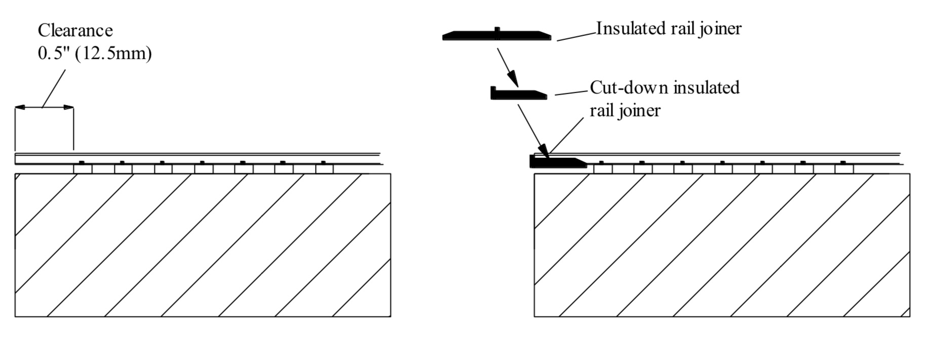 SP4: Treatment of Rail Ends
Rail ends should be firmly fixed to the module surface, for example by soldering to copper-clad ties (sleepers) firmly fixed to the board or by soldering to brass screws.
Clearance of 0.5 inch/12mm should be provided as shown below. This allows a cut-down insulating rail joiner to be slipped onto the rail ends. The purpose of this is to prevent the ends of the rails on adjacent module accidentally touching when they are on different power districts on large layouts. For layouts with only one power district the use of the insulating rail joiners is unnecessary. Cutting the rail joiner in half removes the need to fit it to both rails when two modules are brought together.
SP5: Module end boards
End boards must be between 3.7 and 4.5 inches high. The surface of the end boards must be flat and at right angles to the track bed. The largest area possible should be left clear for clamping. As an absolute minimum the areas shown shaded in the drawings below must be left clear. Sufficient space should be left clear behind the end board for clamping. The end boards of a module must be constructed with sufficient strength to accept an adjacent module being C-clamped to it. At the outer ends of any multiple-board set up, the main running track(s) must be at the prescribed height (see SP7 below) with no gradient, i.e. at 90 degrees to the perfectly vertical end.


SP6: Module sides
The height of a side must match that of an end board at the point where they meet. Apart from this restriction, sides may be any height and their top may extend above or below the track to allow for fills, cuts, bridges etc.
SP7: Module height
The nominal rail-head height is 45 inches. The actual baseboard top surface is thus lower by whatever track bed is used.
SP8: Supports
Legs must be fitted with adjusters that allow the rail-head height to be adjusted in the range 44.5” to 45.5”. Modules must be self-supporting at their outer ends and not ‘lean’ on an adjacent module. Boards with a single leg unit are allowed within a multi-board module.
SP9: Track
Main line tracks must be code 83 (Peco code 83 is suggested as it is easy to obtain in the UK). Spurs and sidings can use other rail sizes.
Dimensions of turnout flange ways etc. must follow the appropriate NMRA standard.
SP10: Track Geometry
Main tracks, or any other tracks designed for use by through trains, must have at least 36” radius curves and #6 turnouts (#3 for Y-turnouts). Spurs and industry tracks must be at least 24” radius and can use sharper turnouts.
The straight between reverse curves must be 12” minimum. There must be no main line gradients.
SP11: Scenery
In order that visual continuity across module joints is not compromised, scenery at module ends must be roughly flat with no features (such as roads, rivers or track other than the modular tracks) crossing module joints
SP12: Roadbed
Main lines should be on roadbed whose thickness should be in the range 3mm to 5mm.
5.2 Module Requirements – Electrical
The majority of this section assumes a DCC system. Guidance note 1 addresses existing modules with analogue wiring.
5.2.1 Concept
Multi Group Set-upsThe idea, for multi-group set-ups is that a set of standardised busses will connect all the modules in the layout. Any consistent dcc system can then be plugged into these busses. For example, one event may use Digitrax command station, boosters and throttles. Another event may use all NCE and so on.
Any consistent DCC system (command station, boosters, throttle panels and throttles) may be connected to these buses for local group use. However, it may be necessary to fit different throttle panels temporarily to take part in multi- group meets – see Guidance note 3)
A complete set of wiring consists of a track bus, throttle bus and accessory bus. Only two of these busses are mandatory (the track bus and throttle bus). Of these, only the track bus must be built-in to the modules. The throttle bus may be temporary and in this case throttle panels may be clamped or screwed to the modules or legs. Other wiring as specified below may be needed at a multi-group meet but may also be temporary on the day. Some groups will want to build all wiring into their modules and this is to be encouraged.
Individual Groups
If individual groups want to take part in NMRA multi group event they must meet the electrical specification described here. The various wiring and throttle panels can be either permanent, attached to the modules, or in temporary form as described above.
Individual Groups are also allowed to build any system they wish into their modules provided it that it does not prevent their modules meeting this specification. For example a group may wish to build-in Digitrax panels for local use but fit temporary Lenz panels with DIN sockets when taking part in a multi-group meet using Lenz. The Digitrax panels would be redundant and disconnected during the meet. See Guidance note 2 for more details
RS-Tower Modular Group
This specification will allow the new modules to work in RS-Tower set-ups and vice versa.
5.2.2 Electrical Specification – Mandatory
SE1: Track Bus Requirements
The track bus is a two-wire bus that provides commands and power to the locomotives and lighted cars. It should be permanently mounted under the module. At the ends of the module it should be terminated in banana connectors as shown below.
The key parameter is the voltage drop along the bus. This depends on the bus itself, how many locomotives are operating, whether they have sound, whether there are lighted passenger cars and so on. Rail joiners should not be relied upon to pass current and data between track sections. Ideally wire droppers should be soldered to each track section and attached to the track bus below the baseboard surface. The specification below should be adequate for a typical local group with around 90ft of modules and a few trains running. In the unlikely event of voltage drop one solution is to reduce the resistance of the bus by connecting additional bus wires in parallel with the existing ones. Alternatively, the layout should be split into power districts with separate boosters.
 Conductor sizes are minimum that should be provided.
Notes
- Finer wire can be used for the last inch or so to connect to the rails. This allows for less visible rail connections. Suitable wire is 15-amp fuse wire. This should be soldered on and insulated sleeving applied, e.g. heat shrink tubing.
- Wherever possible dropper wires should soldered to the underside of the rail sections – this is best achieved before the track sections are secured in place.
Inter-module connections
There are two options for inter-module connection of the track bus. These are compatible.Option 1
The two track busses are brought to banana sockets at the module ends as shown below. Separate jumper leads, with banana plugs at both ends connect between the modules.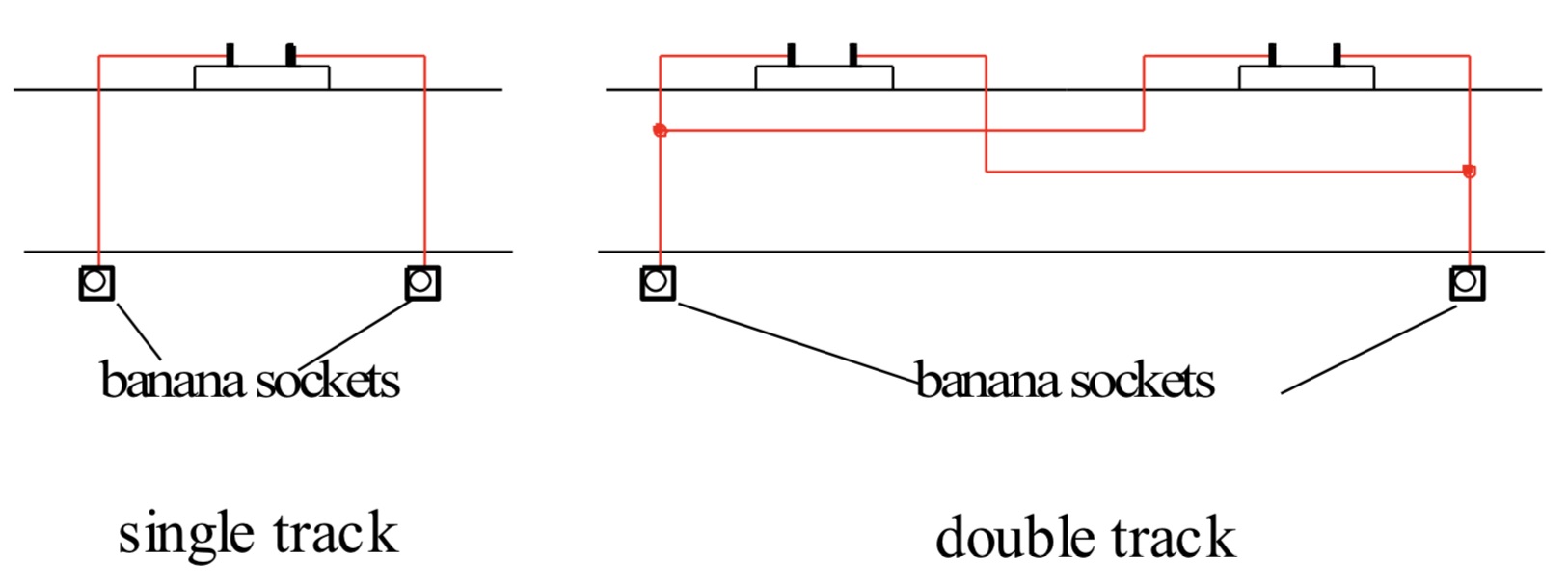 Viewed from the end of the module, the left hand rail(s) should be connected to the left hand banana socket; the right hand rail(s) to the right socket
Option two
In this option, the left hand rail (viewed from the module end) is connected to a banana socket as in option 1. The right hand rail is connected to a flying lead fitted with a 4mm banana plug. This lead should extend 18 inches beyond the module end.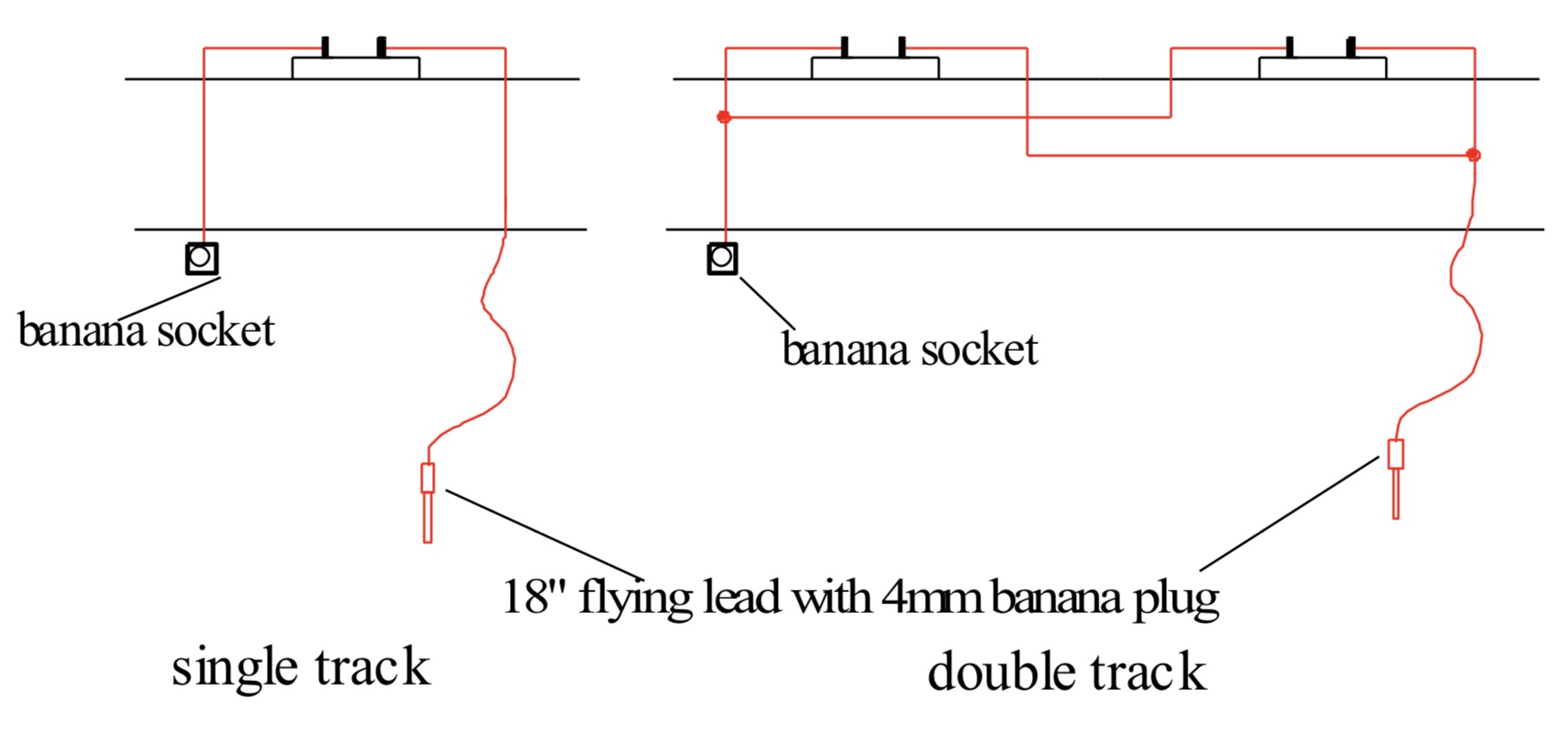 The actual positions in the drawings above are illustrative only. The left and right sockets may be in any positions along the width of the module so long as their relative positions are maintained, i.e. “right rail” on the right. When jumpers are plugged, they should be arranged so that equivalent rails on adjacent modules are connected together.
Track bus colour code
All track bus wiring at the module ends should be red. Since modules are reversible, having different colours for different rails would be likely to cause confusion.
SE2: Throttle Bus
The throttle bus is used to connect the multiple throttles in a system to the command station. It consists of a mutli-core telephone cable and throttle panels. It may be permanently built into the modules (recommended) or a temporary system set up on the day.
SE2.1: Throttle Panels
The throttle panels may be built into the modules or be temporary on the day of a multi-group set-up. If they are temporary they may be clamped or screwed to the module or to the module legs.
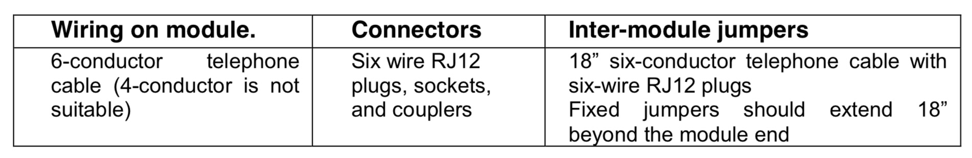
Choice of throttle panel is up to the user and will depend on that used by their local group. For multi-group meets the organisers will specify the type of panels which must be used. Whichever manufacturer’s panels are used, they must be connected using six-conductor telephone cable and RJ12 connectors Four-conductor cable is not suitable. Sufficient slack should be allowed at each panel to allow an alternative, temporary panel to be connected as described in Guidance note 2. For a discussion of the various throttle panels see Guidance note 3In most cases there should be a throttle panel roughly every 10 feet or so along a length of modules. Individual module track plans will dictate the exact needs but thought should be given to placing panels on both sides as modules are, in principle, reversible. Modules shorter than 12 feet should have at least one panel, except those shorter than 2 feet where a panel is unnecessary.
SE2.2: Throttle Bus Wiring
The throttle bus wiring is used to connect between the throttle panels and to connect them to the command station. It may be permanently built into the modules or a temporary arrangement set up on the day.
The throttle bus must be electrically “clean”. Any items connected to it must be appropriate to the system in use and must be only those components intended to connect throttles to the bus, i.e. throttle panels and radio throttle base stations. There must be no other connections.
If it is necessary to extend a telephone cable, an RJ12 in-line coupler should be used. This must be of type that connects “pin 1 in” to “pin 1 out”, pin 2 to pin 2 etc. (an alternative, unsuitable , type reverses the connections so pin 1 connects to pin 6 and so on).
 SE3: Pointwork
Any method of point control may be used. However, any electrical switching in pointwork should use appropriate electrical switches and not rely on point-blade contact. If remote control of pointwork is fitted (for example via DCC accessory decoders) a local means of turnout control should also be provided.
SE4: Mains power
There must be no mains power present on the modules.
Mains electrical equipment should be electrically (PAT) tested and certificated.5.2.3 Electrical Specification – Optional
The items specified below are optional. However, if they are provided, this section defines how they must be implemented.
SE5: Accessory Bus
The accessory bus is a two-wire bus. It carries the same DCC signals as the track bus but is used to control accessories such as stationary turnout decoders. It will normally be powered from a separate booster or circuit breaker. In a small DCC system it can provide both commands to the stationary decoders and power for their accessories such as turnout motors. However, to avoid excessive loading of the bus on large layouts is recommended that modules should only use the bus to receive commands. Power should be provided locally where possible. A convenient way to do this is to power all the accessories on a module from a local “dumb booster” that gets its input signal from the accessory bus.
Where accessories are used on a module, the accessory bus should be built into the module. If accessories are not used, a by-pass cable should be provided when an accessory bus is needed for other modules in the system. This may be permanently built into the modules (preferred) or a temporary arrangement set up on the day.
Conductor sizes are minimum that should be provided.Position of connectors
If the accessory bus is thought of as two parallel wires then the left hand wire should be connected to the left hand Power Pole connector and the right hand one to the right hand power pole connector. The power poles should not be clipped together to form a single connector for transport as this can lead to unexplained short circuits if they are not unplugged.
Accessory bus colour code
Both accessory bus wires should be different colours of the owner’s choosing, clearly marked or tagged.
SE6: Common wire
The previous release of this specification included the requirement for a “common wire”. This was intended to provide a “booster common” connection in multi-booster systems. This requirement has been removed to allow greater flexibility to booster system design on large layouts – see Guidance note 2
For modules built to the earlier specification and having a common wire fitted, this may be removed or left in place as the owner prefers.5.2.3 Physical implementation
SE7: Position of Sockets
Connectors must be positioned such that they do not interfere with module clamping or with the module legs.
SE8: Temporary wiring
If temporary wiring is used for any of the busses this must be fixed at module height (for example by hanging on cup hooks under the module) and not draped on the floor.
6 Module Recommendations
6.1 Module Recommendations – Physical
Curve and point specifications are the minimum allowed. Trains will look better on larger curves. If you are building a module with a curved mainline then adding transition curves will be very beneficial to smooth operations.Back scenes are optional. They look nice on single-sided scenes but this specification allows modules to be connected in either direction. This means a curved module can become an inside or outside curve, which makes backdrops problematical.
6.2 Module Recommendations – Electrical
Non-DCC accessory power
Some existing modules use 16volt ac for point motor control or other accessories. Under normal circumstances these can still be used in a multi-module set-up. To avoid problems, a competent person should check this.
Solid wires
Where on-board conductors use solid wires, it is recommended that soldered connections or insulation-displacement connectors be used in preference to screw terminals. (Suitable insulation displacement connectors are known as ‘Snap-Lock” or “Suitcase” connectors).
Turnouts
For new modules it is recommended that turnouts should be wired in the so-called “dcc friendly” configuration. Members will have their own preferences for electrified and insulated frogs but they should adopt the best practices for each to make them as DCC-friendly as possible. For example, Peco electro-frog turnout packaging includes the manufacturer’s recommendations for making them DCC-friendly. This involves adding wires across the closure and stock rails and snipping the wire connecting the switch rails to the frog rails. Some manufacturer’s products are supplied DCC-friendly and no additional wiring is required – see Shinohara and some Atlas crossings, for example.
Guidance note 1: Connection of pre-existing modules Adapter Boards
Adapter boards are used to connect existing double or single-track modules to modules built to this new specification. Pairs of adapter boards may also be used to connect between existing modules having different standards from each other.
The outer end of the adapter board must meet the specification as set out in this document. The inner end of the adapter board will meet the specification of the existing adjacent module.
Adapter modules must be self-supporting at their outer end and must meet the module specification above for height adjustment.
Module Height
Most existing modules have 40” as the rail-head height. It is hoped that future large set-ups will use 45” because of its improved working height and it is the RS Tower standard. The leg arrangements of existing modules will need to be changed to accommodate this. This should be easily achieved with bolt on extensions.
Existing NMRA modules and analogue wiring
Most existing modules have double track with a bus for each track. At present, some groups use both tracks for analog; some use both for dcc while others use one for each. The existing NMRA specification keeps the two main line busses electrically separate, which allows this.
For use in a multi-group system these two buses can be used to provide the DCC track bus required by this specification. However, they must be connected together to provide a single bus. As these older modules will need adapter boards to connect to the rest of a multi-group layout the connection of the two buses can most conveniently be done there.
A check should be made to confirm that the existing buses are of sufficiently heavy gauge wire. If a bus wire on the module is too light, a wire conforming to this specification should be added in parallel with the existing one. This should run from the bus connector at one end of the module to the bus connector at the other. However, when assessing the suitability of bus wires on existing modules remember that the two existing busses will be connected together in parallel. This will make the bus equivalent to a single wire of twice the cross-sectional area.
It is unlikely that existing modules will have the necessary accessory and throttle busses. In a multi-module set-up their owners will need to provide a temporary cable with the appropriate connectors so that the busses can be passed across their modules. Note that a single by-pass cable can by-pass a whole group of modules if necessary.
Guidance note 2: Suggestions for multi-group meets
This section describes how a multi-group meet might be organised. It reflects thinking in 2013. The rapid changes in technology may offer better alternatives as time progresses. For example “NMRA bus” is currently under development in the USA.
- 1) The host group will put out a call for modules, stock and electrical equipment for the planned meet. They will define at this stage which DCC system will be used on the day. This will define the throttle panels to be used. The group may also define the era. For example “1980’s”, “steam”, “free-for-all” etc.
- 2) Participants will provide details of the modules, throttles, stock etc. they can offer. A suggested pro-forma covering the electrical details is shown in Guidance note 4. Some participants may need to arrange for temporary throttle panels if their permanent ones aren’t compatible with the planned system (see SE2.1). They may also need to provide temporary “by-pass” cables for the accessory bus (see SE5).
- 3) The host group will decide on a suitable layout and electrical design for the day and will inform the participants what they need to bring (e.g. throttles, cables, stock etc.).
- 4) For large systems, the designer of the electrical system will need to determine the number and position of additional boosters and the wiring between them. This will need to take into account the particular DCC system in use and type of boosters available.
- 5) For Lenz and NCE meets all modules must be provided with compatible throttle panels. Lenz LA152 panels are compatible with both. It will be necessary for Digitrax users to fit a temporary panel on the day to run on Lenz or NCE systems.
- 6) For Digitrax meets it is recommended that a combination of Digitrax radio and infrared throttles are used. This means that the throttle bus will no longer be needed for throttles and visiting NCE and Lenz users will not need to make changes to their modules. The organisers will need to provide one or two wired throttles for their own emergency use.
- 7) On the day, the layout will be assembled, checked by the host group, and powered on. If everything conforms to the specification and has been correctly assembled, it should all work.
- 8) It is anticipated that there will be a “Run Chief” on the day who will oversee the initial testing and subsequent running.
In most cases the host group will provide both a DCC system and a Wi-Fi system connected to it. This will enable operators to control trains via smart phones, iPods etc. if they wish.
Over time it is hoped that Wi-Fi will become the normal method for running trains at multi-group meets. In this situation the hosts will provide the command station, boosters and Wi-Fi___33. There will no longer be any need for a wired throttle bus, which means and there will be no longer be a need for anyone to fit temporary throttle panels.
Modules built to variations of the existing NMRA standard
Adapter boards (see Guidance note 1) and higher legs may be needed to allow the modules to connect properly with the rest of the layout. Provision of these will be the responsibility of the modules’ owners.
It is most likely that temporary wiring will be needed. Again, the owners of the modules will be expected to provide this.RS Tower modules
There is no need for Adapter Boards. Temporary accessory bus wiring will be needed, however. The module owners will provide this.
Guidance note 3 Throttle panels
Each of the three major manufacturers has its own design of throttle bus and throttle panels. In some cases one manufacturer’s panel will work with another manufacturer’s system (i.e. with their command station and throttles). However this compatibility is very limited as explained below. There are two situations to address.
- 1) A small system where the throttle bus only needs to be powered by the command station.
- 2) For large systems with long throttle busses and many throttles, some form of “repowering” of the throttle bus is necessary. This is because of voltage drop down long throttle busses with many throttles connected. Digitrax has a different approach from NCE and Lenz for this repowering.
 In view of the above the following approaches are suggested:-
- 1) If you normally use Digitrax and go to a NCE or Lenz based meet (with or without repowering) fit a temporary Lenz panel.
- 2) If you normally use Lenz LA152 panels and go to an NCE based meet (with or without repowering) you don’t need to do anything. If you have repowered the +12 volts on the Lenz bus you should discuss this with the meet organisers to check it will not cause problems. If you go to a Digitrax meet you will need to fit a temporary Digitrax panel unless the meet organisers have decided to only use Digitrax radio and/or infra-red and/or Wi-Fi throttles, in which case you don’t have to do anything.
- 3) If you use NCE and are building new modules, use Lenz LA152 panels rather than NCE/Tony’s ones. You will then not need to make any changes when going to NCE or Lenz meets (repowered or not). For Digitrax meets (repowered or not) you will need to fit a temporary Digitrax panel unless the meet organisers have decided to only use Digitrax radio and/or infra-red and/or Wi-Fi throttles, in which case you don’t have to do anything.
- 4) If you have a module already fitted with NCE/Tony’s panels you will be able to operate without any change at NCE meets and Digitrax meets that don’t involve bus repowering. If Digitrax repowering is involved you will need to fit a temporary Digitrax panel unless the meet organisers have decided to only use Digitrax radio and/or infra-red and/or Wi-Fi throttles, in which case you don’t have to do anything. You would be able to operate at Lenz meets (repowered or not) by fitting an RJ12 to DIN convertor to each NCE/Tony’s panel. It will probably prove easier to just fit a temporary Lenz panel on the day.
This module specification allows modules to be reversed and it is a good idea to have a throttle panel on each side of the module. However, when temporary panels are needed it may only be necessary to fit them on one side of the modules, depending on the geometry of the planned layout. This will keep down the cost of taking part in a multi group meet.
Guidance note 4: Suggested pro-forma for electrical details
The sheet below has been used successfully to gather information from meet attendees and is offered as a suggestion. Feel free to modify it as you see fit.
Module description
Please expand this document and tables or provide additional sheets as necessary(Please note references to “NMRA specification” refers to the latest, unpublished, draft)
Module owner _________________________________________ Module name _________________________________________ Overall Dimensions_________________________________________
Physical
Does the module conform to the NMRA British Region physical specification – dimensions, track position etc.? If not, how does it vary from the specification? (For electrical questions, see later)?
Will you provide clamps to join to adjacent modules?
Electrical Track bus
Accessory bus
Throttle bus


Do the connections to the track bus conform to the NMRA spec? If not, what do you have? How is it wired?

Are there any other connections to the track bus in addition to the track and frog switches?
Will you provide “jumpers” to adjacent modules

Does your module have an accessory bus?
If yes, does it conform to the NMRA spec? If not, what do you have? How is it wired?
What does it connect to on your module
What are the accessory addresses
Will you provide jumpers to the adjacent module

Does your throttle bus conform to the NMRA specification
Does your throttle bus connect to adjacent modules using RJ12 (telephone) connectors. If not, what does it use?
What type of throttle panels/radio base stations does your module have?
We will be using xxx DCC system. Will you be providing any throttles? How many? Type(s)?
Are there ANY other electrical connections to the throttle bus besides throttle panels and radio base stations?

Will you provide jumpers to adjacent modules (Track, accessory, throttle)
Other electrical connections
Please describe any other electrical equipment (e.g. power supplies) and how it is connected