Hey Jim,
Research or otherwise that's one large volume of timber in that there trestle - good luck and looking forward to the story of the build.
Regards Dean
Winter 2016 Challenge - Jim Botten - Breakheart Trestle
Forum rules
This is for all registered members with access to the forum. (This is everyone who subscribes to Region Services).
Online modeling competitions and challenges will be announced here.
Members must report and document their modeling progress here.
Winners will usually be chosen by one of the following two (or a combination of the two)
-NMRA-BR BOD members
-Via a voting Poll on this forum by the membership.
At the end of each competition, the entries will be moved to the relevant modeling section to facilitate access of the general public.
-
deanobeano
- Posts: 77
- Joined: Fri Oct 09, 2015 4:22 pm
-
PeterBowen

- Posts: 124
- Joined: Fri Jul 03, 2009 7:05 pm
- Location: Wells, Somerset
- Contact:
Re: Winter 2016 Challenge - Jim Botten - Breakheart Trestle
Jim,
Well done for accepting the challenge. If you need more lumber I found a good source used by model airplane builders at http://www.slecuk.com/
As for staining the bents I found using shoe dye and rubbing alcohol worked very well to get the aged and weathered wood look.
Peter
Well done for accepting the challenge. If you need more lumber I found a good source used by model airplane builders at http://www.slecuk.com/
As for staining the bents I found using shoe dye and rubbing alcohol worked very well to get the aged and weathered wood look.
Peter
-
PeterBowen
- Posts: 124
- Joined: Fri Jul 03, 2009 7:05 pm
- Location: Wells, Somerset
- Contact:
Re: Winter 2016 Challenge - Jim Botten - Breakheart Trestle
Jim,
This might help you:
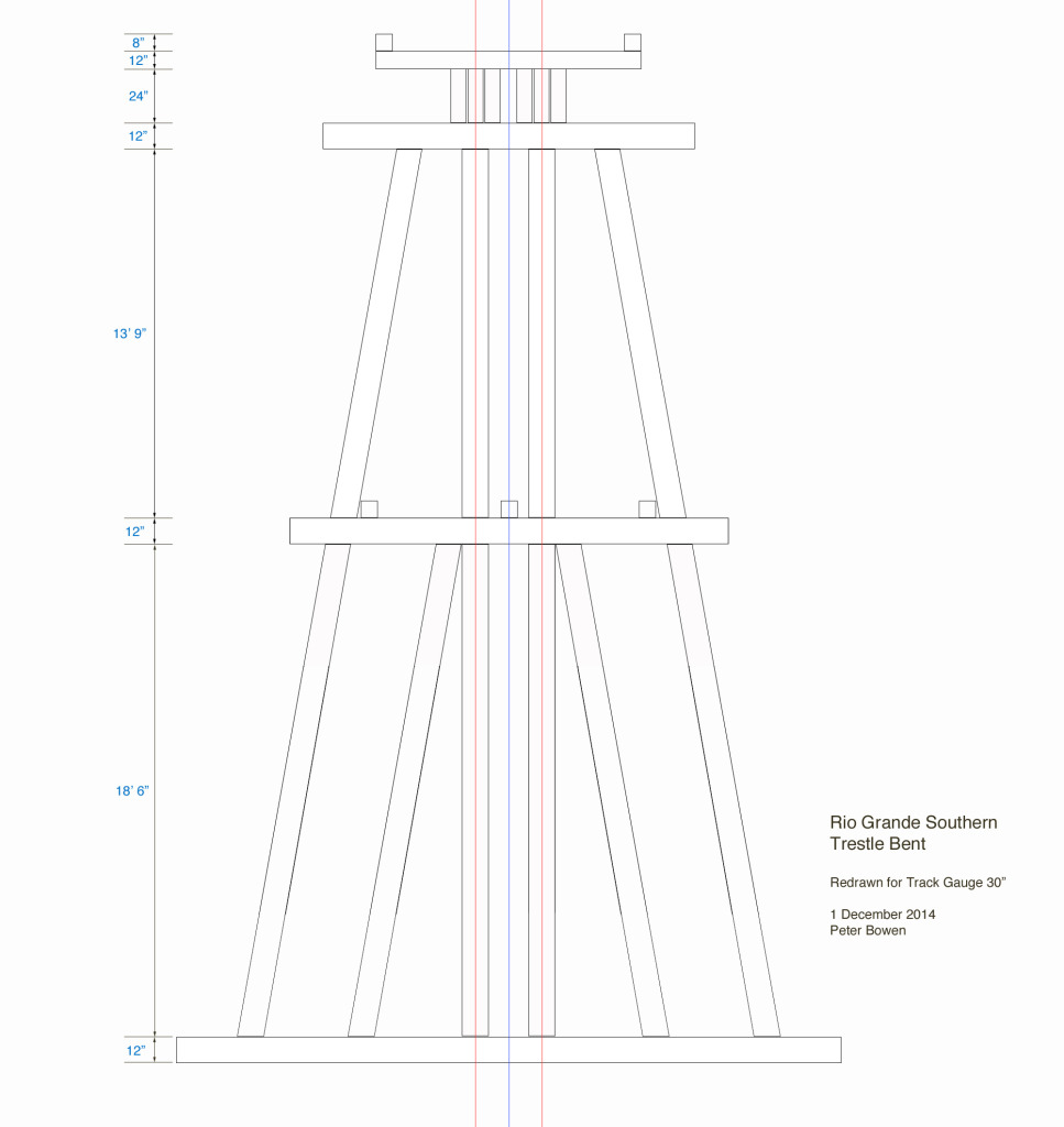
Prototype Rio Grande Trestle details
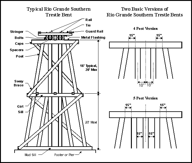
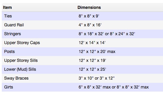
Construction Methods
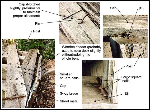
This sketch below shows the method used by the RGS to tie the bridge bents together. This style of construction has been observed at all of the major bridge sites on the railroad that contain enough material for examination. It is also evident in the water towers still standing.
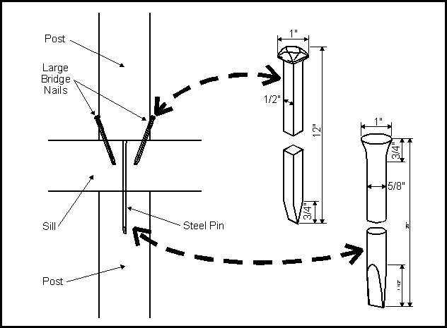
A cap was attached to the posts underneath it by driving a round steel pin down through the cap and into the post. This was done for each post and for each story of every bent. Anywhere from one to three small bridge nails (9" long with 3/8" shaft) were used to attach the sway braces to the posts. These sway braces ran from the lower left to upper right. This unit or story was often assembled off to the side and then moved into position on the bridge.
Each storey was attached to the one below by toe nailing several full sized bridge nails through the post and into the cap of the story underneath. In the bottom story, the mud sill would probably be attached before the story was moved into place. As each storey was positioned and attached to the storey below, girts were added between the bents to stabilise them.
When finished these bridges were strong and stable. The bridge at Ames, (43A), which was built in a very precarious location, stood for almost thirty years with no maintenance whatsoever.
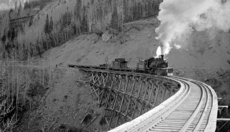
Rio Grande Southern Railroad had 142 bridges scattered along it's 162 miles of track . The most spectacular bridge was 9A. This wooden trestle was 836 feet long and had a 202 foot Howe deck truss in the centre. It was 134 feet high, prompting the early crews to call it the high bridge. The original 9A strained the capabilities of wooden bridge building to their limits and, as a result, it was never really successful. The crews didn't like it or trust it, and neither did management. Unsurprisingly it was among the first of the bridges to be replaced. 9A was removed and replaced with an earthen fill and box culvert in 1903. When this culvert washed away in 1908, it was replaced with the second 9A, which was a more typical curved open deck trestle.
Like 9A, almost all of the original bridges were rebuilt or replaced at one time or another. Most of the Howe trusses were replaced with simple open deck trestles, and many of the smaller bridges were replaced with earthen fills and culverts. By the end of operations, 111 bridges were left on the railroad; virtually none were original. The reasons for replacing a bridge were many, but for the most part, the arrival of heavier motive power or damage caused by weather and high water resulted in replacement.
At a glance, most of the bridges appear to be alike, a closer look however, shows that all differ in detail. The RGS built their bridges following accepted and proven engineering practices. Thus, all of the bridges look similar in overall design.
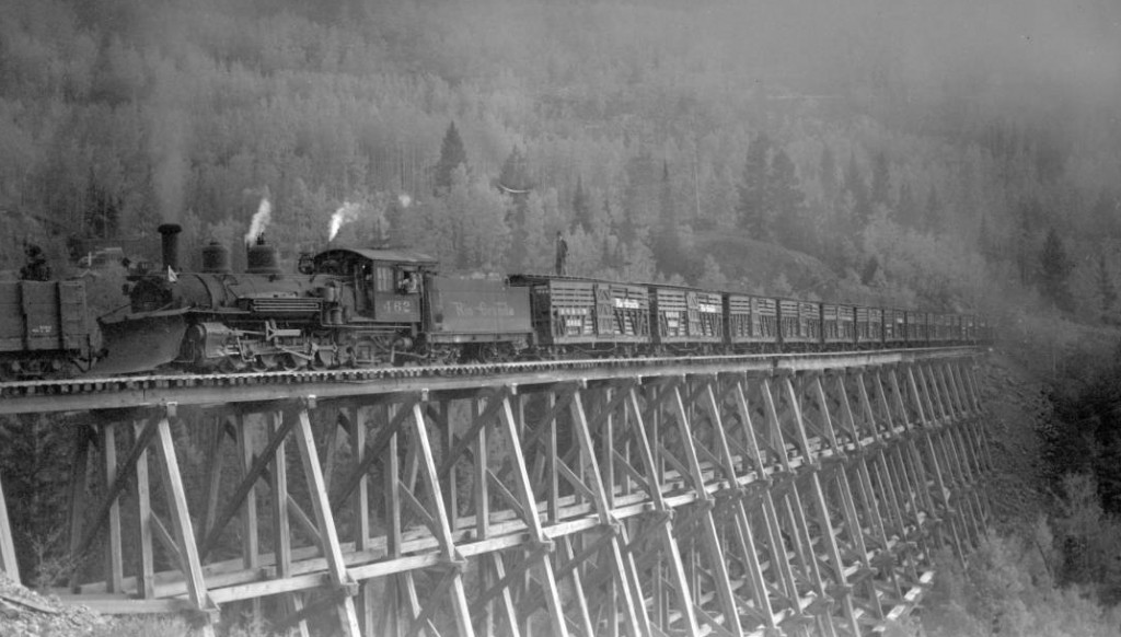
A Robert W. Richardson view of the Butterfly, Colorado trestle Bridge 44A from November 7, 1952
Detail differences in the bridges occurred due to unusual circumstances in placement or geography. Changes also occurred when the bridges were repaired. Thus, over time, all of the bridges slowly changed.
I know that it can be frustrating not having a clear plan for construction so I did my own drawings which might help you:
I hope this helps you, let me know,
Peter
This might help you:
Prototype Rio Grande Trestle details
Construction Methods
This sketch below shows the method used by the RGS to tie the bridge bents together. This style of construction has been observed at all of the major bridge sites on the railroad that contain enough material for examination. It is also evident in the water towers still standing.
A cap was attached to the posts underneath it by driving a round steel pin down through the cap and into the post. This was done for each post and for each story of every bent. Anywhere from one to three small bridge nails (9" long with 3/8" shaft) were used to attach the sway braces to the posts. These sway braces ran from the lower left to upper right. This unit or story was often assembled off to the side and then moved into position on the bridge.
Each storey was attached to the one below by toe nailing several full sized bridge nails through the post and into the cap of the story underneath. In the bottom story, the mud sill would probably be attached before the story was moved into place. As each storey was positioned and attached to the storey below, girts were added between the bents to stabilise them.
When finished these bridges were strong and stable. The bridge at Ames, (43A), which was built in a very precarious location, stood for almost thirty years with no maintenance whatsoever.
Rio Grande Southern Railroad had 142 bridges scattered along it's 162 miles of track . The most spectacular bridge was 9A. This wooden trestle was 836 feet long and had a 202 foot Howe deck truss in the centre. It was 134 feet high, prompting the early crews to call it the high bridge. The original 9A strained the capabilities of wooden bridge building to their limits and, as a result, it was never really successful. The crews didn't like it or trust it, and neither did management. Unsurprisingly it was among the first of the bridges to be replaced. 9A was removed and replaced with an earthen fill and box culvert in 1903. When this culvert washed away in 1908, it was replaced with the second 9A, which was a more typical curved open deck trestle.
Like 9A, almost all of the original bridges were rebuilt or replaced at one time or another. Most of the Howe trusses were replaced with simple open deck trestles, and many of the smaller bridges were replaced with earthen fills and culverts. By the end of operations, 111 bridges were left on the railroad; virtually none were original. The reasons for replacing a bridge were many, but for the most part, the arrival of heavier motive power or damage caused by weather and high water resulted in replacement.
At a glance, most of the bridges appear to be alike, a closer look however, shows that all differ in detail. The RGS built their bridges following accepted and proven engineering practices. Thus, all of the bridges look similar in overall design.
A Robert W. Richardson view of the Butterfly, Colorado trestle Bridge 44A from November 7, 1952
Detail differences in the bridges occurred due to unusual circumstances in placement or geography. Changes also occurred when the bridges were repaired. Thus, over time, all of the bridges slowly changed.
I know that it can be frustrating not having a clear plan for construction so I did my own drawings which might help you:
I hope this helps you, let me know,
Peter